
Movable Scaffolding Systems
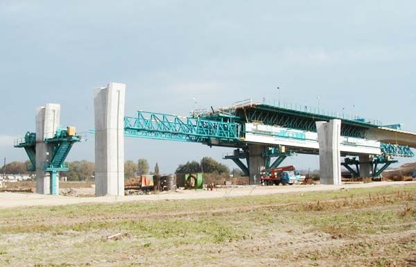
A self-launching system for span-by-span construction of cast-in-place concrete superstructures, on continuous and simply supported bridges, without intermediate supports.
Key specifications
- Span range
- 20–70 mWithout intermediate supports
- Curvature radius
- ≥ 250 mVariable radii of curvature
- Deck depth
- Constant or variableSix cross-section types
- Arrangements
- TwoUnderslung and overhead
What a movable scaffolding system does
A movable scaffolding system carries the formwork for one span of a cast-in-place concrete superstructure, supports it while the span is cast and cured, then releases and launches itself forward to the next span. The system is self-launching, so the sequence repeats without external lifting equipment.
Because the system spans between the permanent piers, no intermediate supports are needed at ground level. That is the property that makes it suitable where falsework from the ground is impractical.
Applications and construction method
The construction method is span-by-span casting of concrete superstructures in place, on both continuous and simply supported bridges. Each completed span carries the system forward to the next.
Bridge cross-sections accommodated
Span range, deck types and design considerations
Range and deck geometry
Swipe or scroll horizontally to view the full table.
| Span range | 20–70 m |
|---|---|
| Intermediate supports | Not required |
| Bridge types | Continuous and simply supported |
| Cross-sections | Double-T, U-shape, single box, multi-cell box, box with struts, composite |
| Deck depth | Constant or variable |
| Horizontal curvature | Variable radii of 250 m or greater |
| Construction method | Span-by-span, cast in place |
Adaptability and design considerations
-
Span-by-span without intermediate supports
Spans of 20–70 m are cast in place without supports between the permanent piers.
-
Variable horizontal curvature
The system is built to handle bridges with variable radii of curvature of 250 m or greater.
-
Different pier heights
The system is built to handle different pier heights along the same structure.
-
Diverse support configurations
It accommodates a range of bridge support configurations.
-
Constant or variable depth
Decks of constant or variable depth are accommodated across the six cross-section types.
-
Internal formwork rolling wagon
The system can be equipped with an internal formwork rolling wagon, also known as a collapsible hydraulic form-trolley, for formwork operations inside the box.
Underslung and overhead arrangements
The system is supplied in two arrangements. Both perform the same function, and the choice between them follows the configuration of the bridge and the constraints of the construction site.
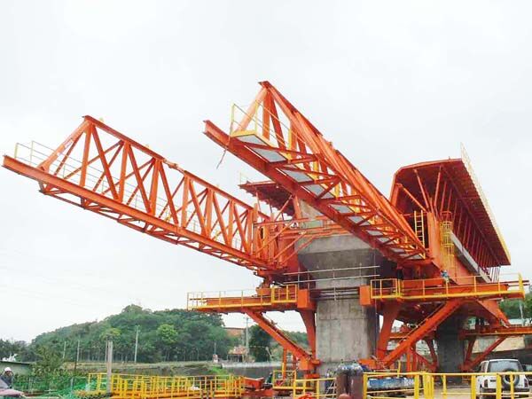
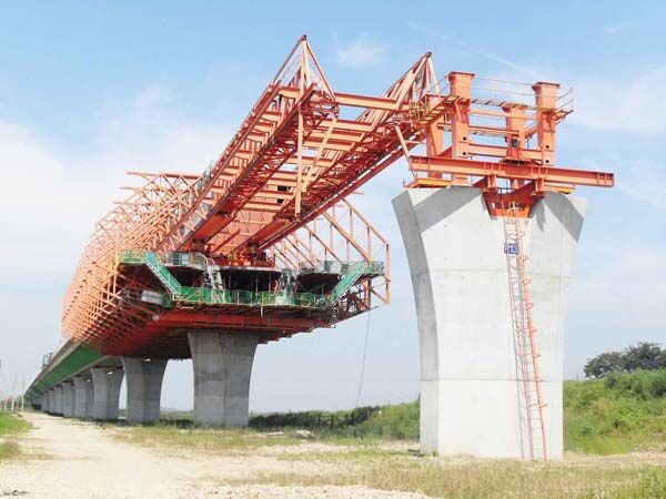
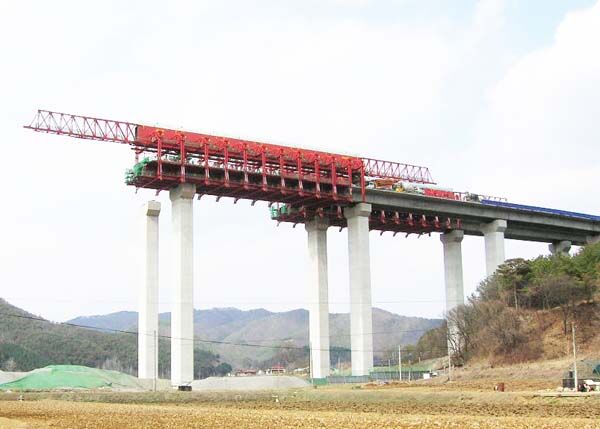
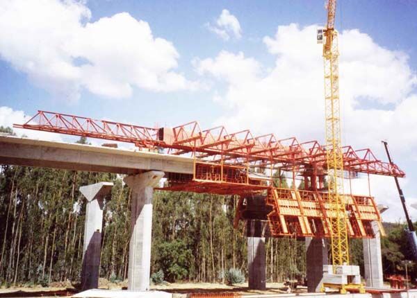
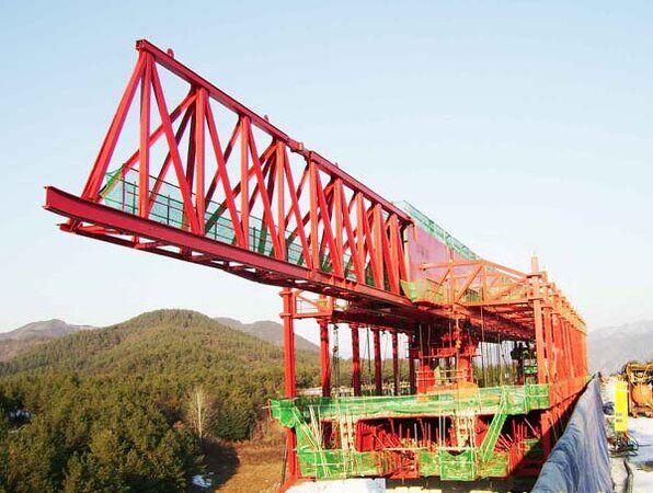
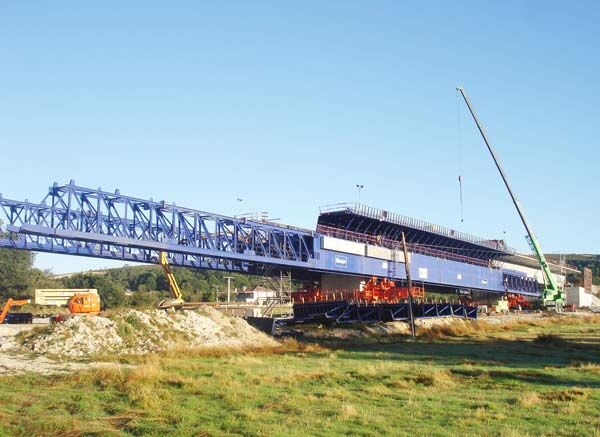
The two differ in where the main structure sits relative to the deck. The table below describes what is visible in the photographs beneath it.
Swipe or scroll horizontally to view the full table.
| Underslung | Main girders positioned at or below deck level, carried on brackets bearing on the piers. |
|---|---|
| Overhead | Main truss positioned above deck level, with the formwork suspended beneath it. |
Selecting between the two arrangements is project-specific and is settled by engineering assessment of the bridge configuration and the site constraints.
Movable scaffolding systems in service
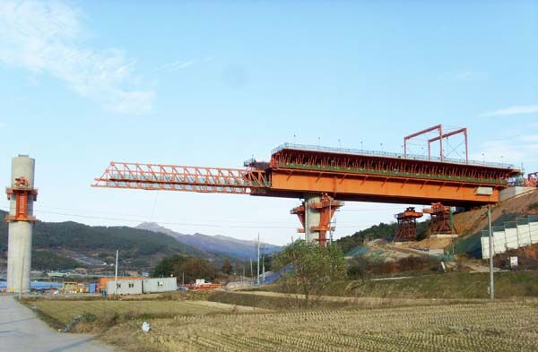
Systems in both arrangements, showing the main structure, the pier supports and the formwork in position.
Related equipment
Discuss your movable scaffolding requirement
Tell us the span arrangement, the deck cross-section and the site constraints, and our team will respond to your enquiry.